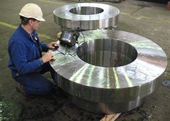
Ultrasonic Testing (UT)
Ultrasonic testing uses the same principle as is used in naval SONAR and fish finders. Ultra-high frequency sound is introduced into the part being inspected and if the sound hits a material with a different acoustic impedance (density and acoustic velocity), some of the sound will reflect back to the sending unit and can be presented on a visual display. By knowing the speed of the sound through the part (the acoustic velocity) and the time required for the sound to return to the sending unit, the distance to the reflector (the indication with the different acoustic impedance) can be determined. The most common sound frequencies used in UT are between 1.0 and 10.0 MHz, which are too high to be heard and do not travel through air. The lower frequencies have greater penetrating power but less sensitivity (the ability to "see" small indications), while the higher frequencies don't penetrate as deeply but can detect smaller indications.
The two most commonly used types of sound waves used in industrial inspections are the compression (longitudinal) wave and the shear (transverse) wave, as shown in Figure 10. Compression waves cause the atoms in a part to vibrate back and forth parallel to the sound direction and shear waves cause the atoms to vibrate perpendicularly (from side to side) to the direction of the sound. Shear waves travel at approximately half the speed of longitudinal waves.
Sound is introduced into the part using an ultrasonic transducer ("probe") that converts electrical impulses from the UT machine into sound waves, then converts returning sound back into electric impulses that can be displayed as a visual representation on a digital or LCD screen (on older machines, a CRT screen). If the machine is properly calibrated, the operator can determine the distance from the transducer to the reflector, and in many cases, an experienced operator can determine the type of discontinuity (like slag, porosity or cracks in a weld) that caused the reflector. Because ultrasound will not travel through air (the atoms in air molecules are too far apart to transmit ultrasound), a liquid or gel called "couplant" is used between the face of the transducer and the surface of the part to allow the sound to be transmitted into the part.

UT Techniques
Straight Beam

Angle Beam

Angle beam inspection uses the same type of transducer but it is mounted on an angled wedge (also called a "probe") that is designed to transmit the sound beam into the part at a known angle. The most commonly used inspection angles are 45o, 60o and 70o, with the angle being calculated up from a line drawn through the thickness of the part (not the part surface). A 60o probe is shown in Figure 12. If the frequency and wedge angle is not specified by the governing code or specification, it is up to the operator to select a combination that will adequately inspect the part being tested.
In angle beam inspections, the transducer and wedge combination (also referred to as a "probe") is moved back and forth towards the weld so that the sound beam passes through the full volume of the weld. As with straight beam inspections, reflectors aligned more or less perpendicular to the sound beam will send sound back to the transducer and are displayed on the screen.
Immersion Testing
Through Transmission

Phased Array
Time of Flight Diffraction

